Building an AI Chess Board
Saturday, March 28, 2026
This project is a modular smart chess board prototype built around three core requirements: direct square sensing, square-level visual feedback, and a software stack capable of interpreting the board as a legal chess position rather than a loose collection of piece locations. The current system is organized around four repeated 4×4 modules, each integrating Hall-effect sensing, LED support, local power conditioning, and a reduced communication interface. On the software side, the board is backed by a Java chess core built around bitboards, packed moves, and legality filtering -- all validated by PERFT.
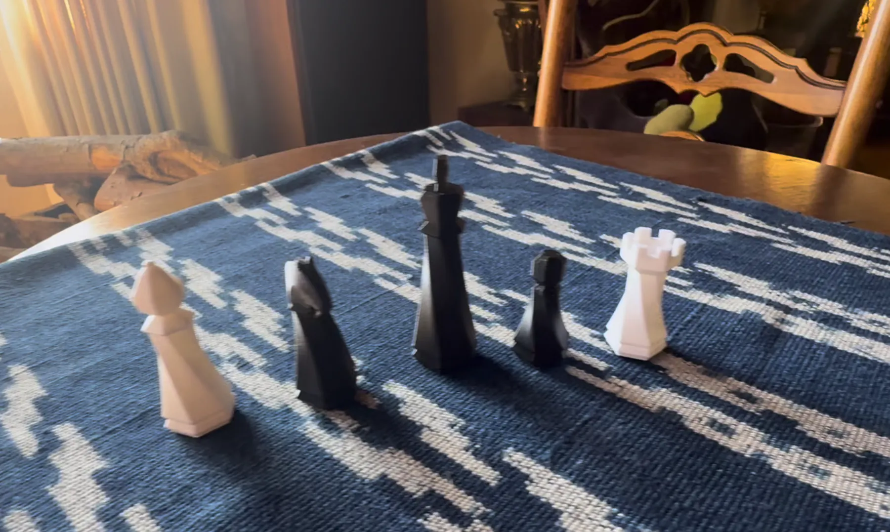
System Architecture
The most important hardware decision in the project was moving away from per-square modularity and toward four identical 4×4 blocks. At full board scale, square-level modularity multiplies PCB overhead, connectors, and assembly complexity too aggressively. A 4×4 module, by contrast, is large enough to justify local support electronics and small enough to remain manufacturable, routable, and easy to replicate.
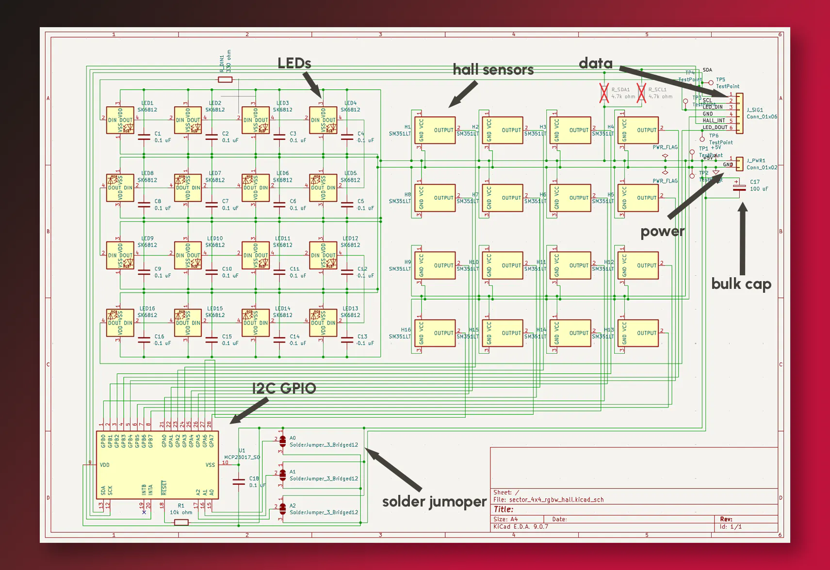
Each 4×4 block contains:
- a Hall sensor per square for magnetic occupancy detection
- an LED per square for visual feedback
- per-square local decoupling capacitors
- a bulk input capacitor near the module power entry
- an I2C-based GPIO expansion layer to reduce board-level signal count
The result is a cleaner board-level architecture: instead of exporting a large number of raw signals from every square, each module concentrates its local I/O and exposes a much smaller interface to the controller.
I2C and Local Data Handling
The use of I2C is central to the 4×4 design. Without local aggregation, each module would require a far larger number of direct sensor and lighting connections, which would make scaling to the full board unnecessarily cumbersome. By handling that complexity locally and exposing shared data lines plus power, the prototype stays electrically manageable and mechanically cleaner.
This also makes the hardware genuinely modular. The same PCB can be reused across all four quadrants, with local address selection allowing identical modules to occupy different physical positions in the full 8×8 system.
That is the broader philosophy behind the board architecture: keep complexity inside the repeated module so the full-board system remains tractable.
Power Distribution and Decoupling
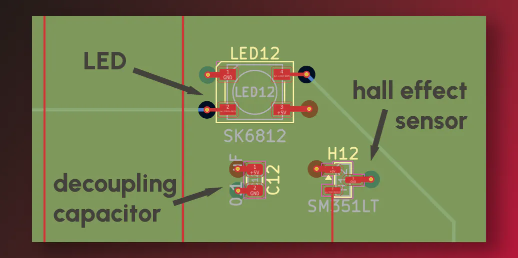
The decoupling strategy is similarly deliberate. Each square includes a local decoupling capacitor, while the module input includes a larger bulk capacitor near power entry.
These serve different roles:
- the bulk capacitor stabilizes the module against slower or larger transient demands
- the local capacitors keep square-level disturbances near the point of load
In a dense mixed-function board — especially one combining repeated sensors and LEDs — this matters. The goal is not simply to add capacitance, but to prevent small local switching events from becoming shared board-level noise.
PCB Layout
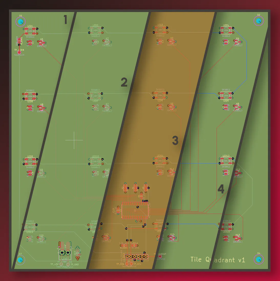
The module is implemented as a four-layer PCB. The inner layers are dedicated to GND and +5V, stitched with vias to provide short return paths and cleaner distribution across the board. Hall-sensor routing is prioritized on one side, while the LED chain is largely routed on the other.
This partition keeps the sensing paths cleaner, even if it produces a less intuitive channel order from the software side. That trade is worth making. Hardware should optimize for signal integrity, routing clarity, and manufacturability first; logical remapping is far cheaper in software.
Mechanical Stack
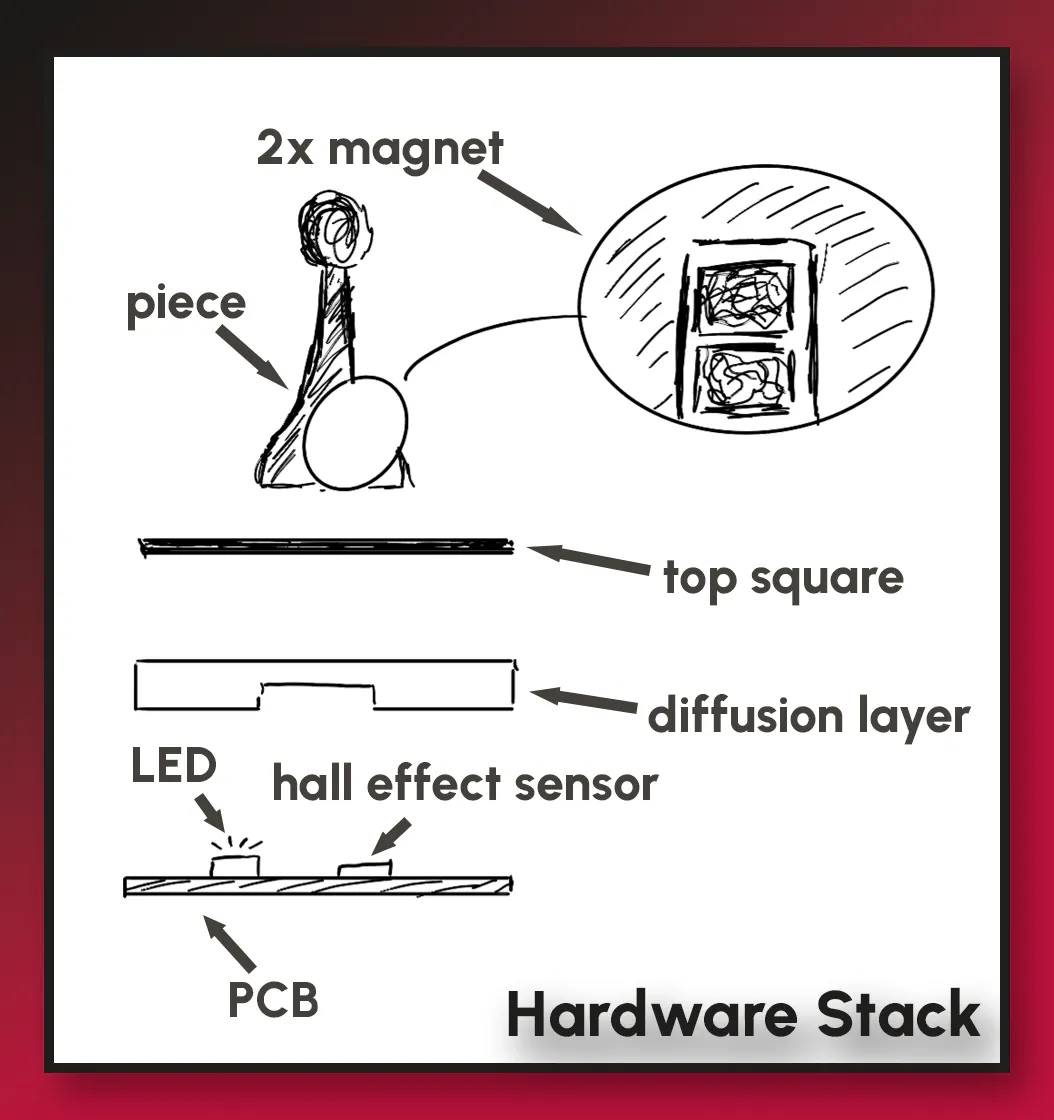
The mechanical design is built around the PCB rather than around a decorative shell. Each 4×4 housing mounts directly above the module and defines the sixteen square cells. Each square uses a layered top assembly consisting of:
- a diffusion layer for optical smoothing
- a colored top insert for the visible board surface
The chess pieces are modified to hold two stacked 5×2 mm neodymium magnets, giving the Hall sensors a consistent magnetic field to detect through the stack. At this stage, the hardware is solving the occupancy problem rather than the piece-identity problem; the engine is responsible for interpreting what a legal change in occupancy means.
Software Model
The software side of the project is built around bitboards. The board state stores side occupancy, per-piece masks, turn information, and transient rules such as en passant:
public long white, black;
public long pawns, knights, bishops, rooks, queens, kings;
public boolean whiteTurn;
public long enPassantMask;
This is a natural fit for chess: 64 squares map directly onto the 64 bits of a Java long. More importantly, it aligns well with the physical board. The hardware reports square occupancy; the software maintains the legal interpretation of that occupancy over time.
Move Representation
Move generation is built around a packed integer format rather than a heavier object representation. In MoveGenerator.java, each move is encoded into a single int:
private static int pack(int from, int to, int promoCode) {
    return (from & 63) | ((to & 63) << 6) | ((promoCode & 7) << 12);
}
This gives:
- 6 bits for the source square
- 6 bits for the destination square
- 3 bits for promotion metadata
The packed format keeps generation lightweight, while richer semantics are deferred to the move layer.
Legal Move Generation
The engine follows the standard two-stage approach: generate pseudo-legal moves first, then filter them by king safety.
int[] pseudo = generatePseudoLegal(b, sq);
Board b2 = b.Move(new Move(b, packedToUci(pm)));
if (!isSquareAttacked(b2, kingSq, oppWhite)) legal.add(pm);
Castling receives explicit pass-through checks, and legality is evaluated only after the move has been applied. This keeps the move generator relatively compact while preserving correctness.
The engine also separates fixed-pattern pieces from sliders in the expected way. Knights and kings use precomputed masks, while bishops and rooks use directional traversal:
public static final long[] KNIGHT = new long[64];
public static final long[] KING   = new long[64];
public static final int[] ROOK_DF = { 1, -1, 0, 0 };
public static final int[] ROOK_DR = { 0, 0, 1, -1 };
Pawns are handled separately because they are directional and state-sensitive. Promotion, double pushes, captures, and en passant all live there. One of the cleaner examples is the en passant handling in Move.java:
if (this.to == epTargetSq && !toOccupiedByOpponent) {
    this.capturedSquare = this.movedWhite ? (this.to - 8) : (this.to + 8);
}
That explicit state handling is what keeps special rules from becoming fragile edge cases.
Validation
Board.Move() applies transitions to a copied board, updates en passant state, clocks, and castling rights, and flips the side to move:
if (m.isDoublePush && m.movedType == 'p') {
    int epSq = m.movedWhite ? (m.from + 8) : (m.from - 8);
    b.enPassantMask = 1L << epSq;
}
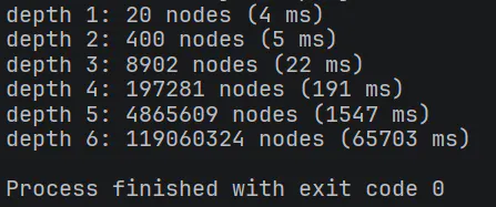
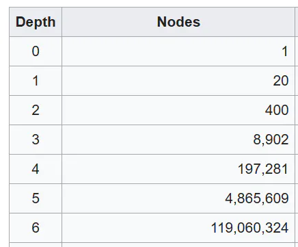
Correctness is then validated with PERFT, which recursively counts legal move trees to fixed depth:
if (depth == 0) return 1L;
for (int pm : moves) nodes += perft(b.Move(m), depth - 1);
For this project, PERFT is not just an engine milestone. It is what makes the hardware meaningful. Once the physical board begins reporting square state, the software receiving that state has to be trustworthy.
Terminal Output:
Expected Output:
Current Status
At this stage, the prototype has a defined hardware/software boundary:
- hardware: modular 4×4 sensing and lighting blocks, I2C-based local data reduction, per-square and bulk decoupling, printed square stack, magnetized pieces
- software: bitboard board model, packed moves, semantic move decoding, legal filtering, attack tables, and PERFT validation
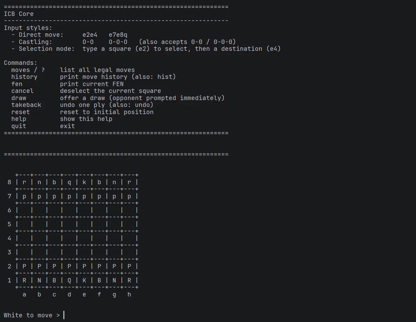
The remaining work is primarily integration: validating the first full 4×4 module electrically, characterizing sensing behavior through the assembled stack-up, then replicating that module across the board and connecting it cleanly to the engine layer.
Closing
What began as a cost-constrained build has developed into a more complete hardware/software prototype: a board with a defined sensing strategy, a repeatable module boundary, a clean communication scheme, a deliberate power-distribution philosophy, and an engine capable of enforcing the rules beneath it.
The full board is not complete yet, but the important threshold has already been crossed. This is no longer just an idea or a rendering. It is now a real system with a real architecture and a clear path to integration.
Links
GitHub: Link
YouTube: Link