Bench
Thursday, August 20, 2026
Bench... and it's not made out of wood?
TL;DR wires are annoying, let's put Bench in the middle of the Arduino workflow.
I love Arduino, it's perfect for prototyping your projects before making your PCBs. But, idk about you, the most annoying thing to me is the fact that the board is tied to my laptop. And it's not a graceful connection, no, these wires are some of the most stale twisted things you've ever used, especially the uni lab ones. This gets even worse when you're using a desktop computer. But what if we put a device in the middle?
Enter: Bench.
Bench is a Wi-Fi upload dock for Arduino (built primarily for the Uno R3 because it's the one I use most). Compile your sketch, run a command, and boom, it uploads to your device somewhere else. No more wire, Arduino dev becomes a little less life-draining.
This is a simple little project, but it's open source, and I hope you find some use out of it. Feel free to leave issues, fork, or really do whatever you want with it.
What’s Bench?
Bench is a Wi-Fi upload dock for Arduino.
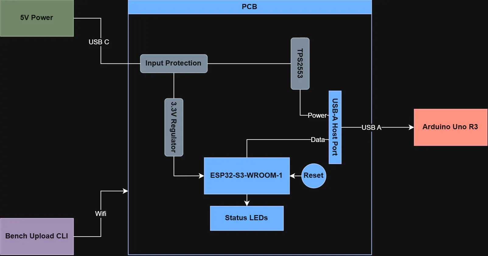
Bench sits between your laptop and Arduino. The laptop sends a compiled Intel HEX file to Bench over Wi-Fi, Bench opens a USB host connection to the Arduino, and uploads the program through the normal bootloader path.
Why I Focused on the Uno R3
I already said this, but it’s my favorite board.
It’s also one of the most documented boards, which was useful for this first prototype. The board uses an ATmega16U2 as the USB-to-serial bridge, and the actual sketch runs on the ATmega328P.
When you upload to an Uno R3 normally, the computer talks through the USB-to-serial interface, triggers the bootloader window, and sends the program to the ATmega328P using the Optiboot/STK500-style upload process.
Bench takes over the role that your laptop normally plays in that chain.
Other boards may be supported in Rev B, with a focus on the nano (I have a nano, yeah I’m pretty biased).
Hardware
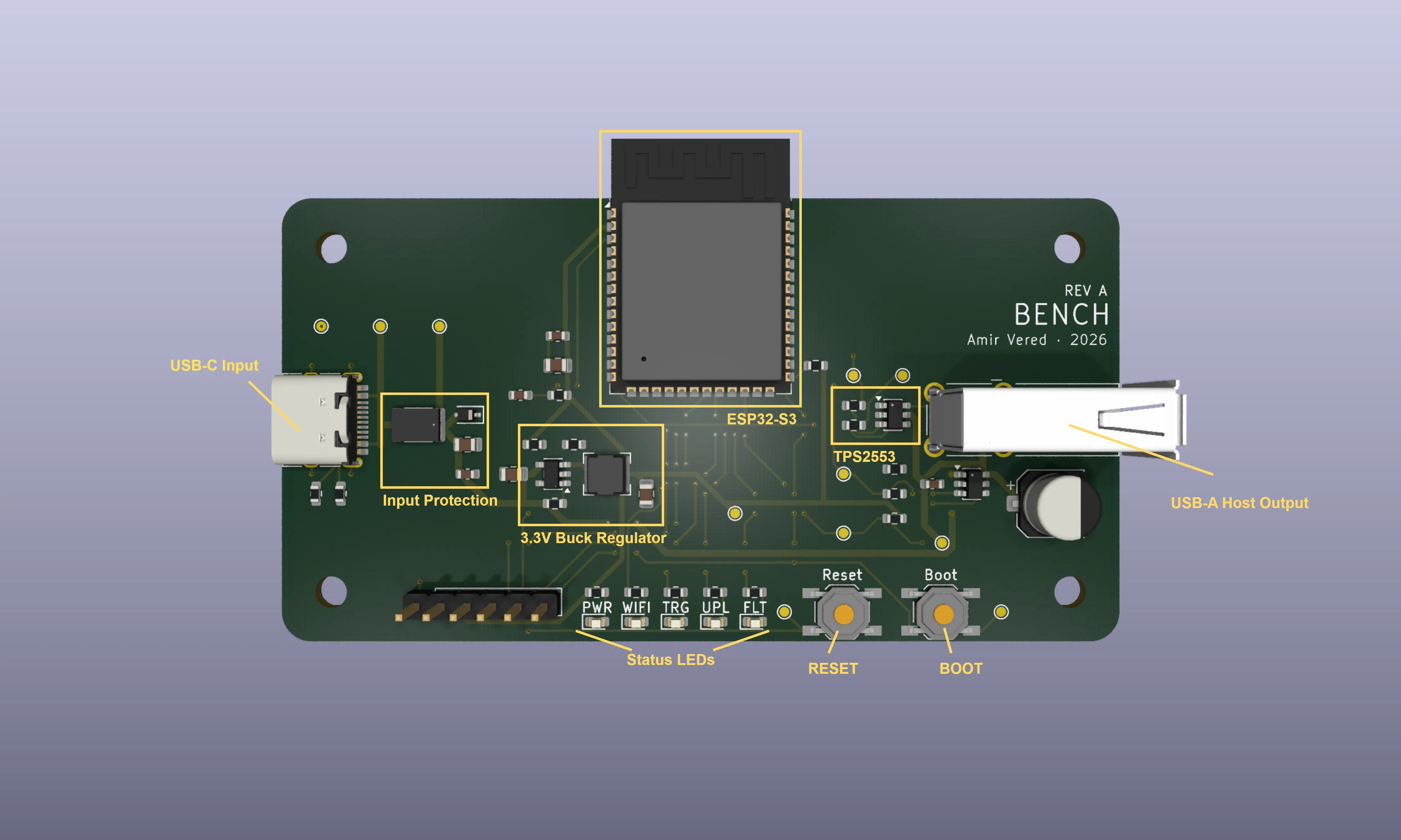
Bench Rev A is built around the ESP32-S3-WROOM-1. The ESP32-S3 handles Wi-Fi, runs the firmware API, and acts as the USB host for the Arduino.
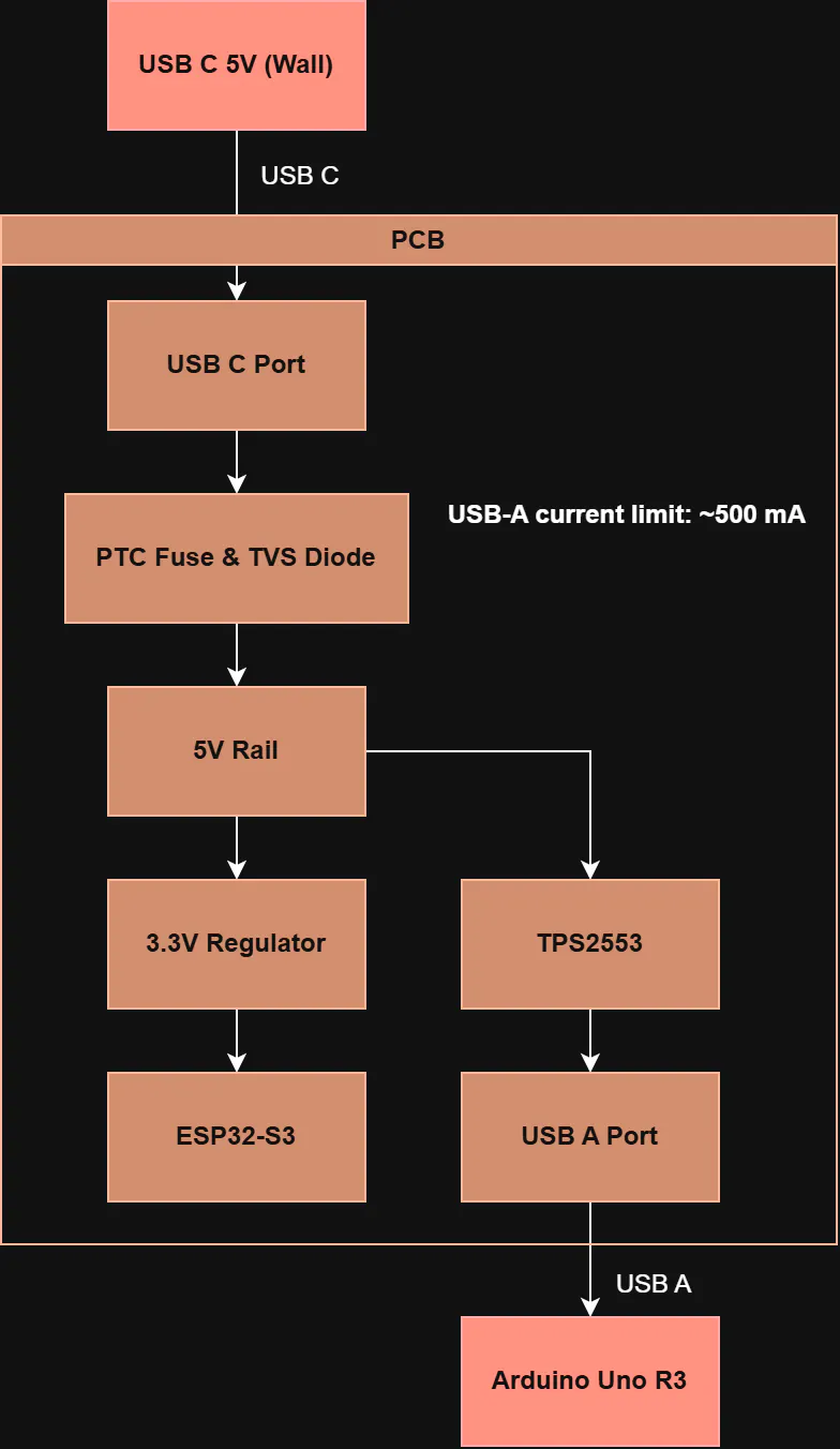
The main hardware blocks are:
- USB-C 5V input
- Input protection with PTC fuse and TVS diode
- 3.3V buck regulator
- ESP32-S3-WROOM-1
- TPS2553 current-limited USB power switch
- USB-A host output
- Status Indicators / Interfaces
Input
The USB-C on Bench is used for 5V power only, intended to be plugged into a wall outlet. The CC pins are grounded through 5.1k pulldowns, and all data pins aren’t connected, so the USB-C sees Bench as a sink.
Input Protection
Bench has some basic input protection before the main 5V rail, including a PTC fuse and a TVS diode.
The PTC fuse protects against overcurrent events, while the TVS diode clamps voltage spikes or transients on the input.
3.3V Regulation
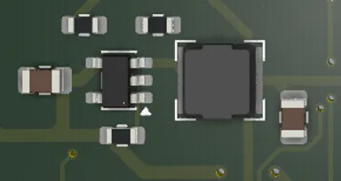
The ESP32-S3 needs a stable 3.3V rail, so Bench steps down the 5V input using a buck regulator.
The regulator used is the TLV62569DBVR and it yields an approximate 3.3V output.
R_top = 453k
R_bottom = 100k
Output = ~3.318V (assuming 0.6V feedback reference)
Wi-Fi chips pull current in bursts, so this part was super important.
ESP32-S3
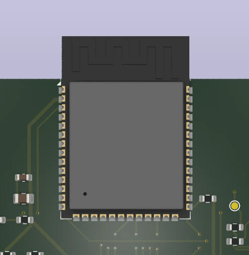
The ESP32-S3-WROOM-1-N8R8 is Bench’s control chip.
It handles Wi-Fi connection, HTTP API, uploading, target power control, status LEDs, and USB host communication.
GPIO assignments:
Wi-Fi LED: IO13
Target LED: IO14
Upload LED: IO15
Fault LED: IO16
TPS2553 FAULT: IO47
TPS2553 EN: IO48
I hadn't worked with an ESP32-S3 before, so this was cool to learn about.
Target Power Regulation
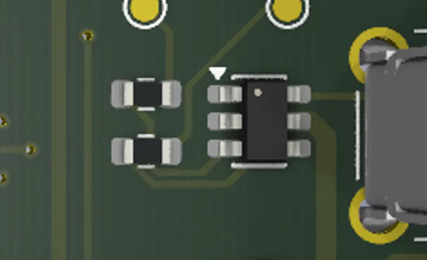
One of the bigger decisions in this project was how to power the output USB.
As I didn’t want it tied directly to the 5V rail, I instead used a TPS2553 current-limited USB power switch.
That way, Bench has actual control over the target port. The ESP32-S3 can turn target power on or off, and it can also detect fault conditions from the TPS2553.
Current is limited to ~500 mA by setting RILIM = 59k.
This makes Bench a bit safer, and also easier to handle with nuance.
Output
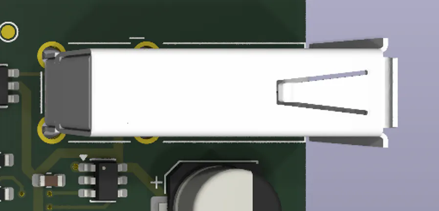
Arduino connects to Bench just using a normal USB-A cable. Bench, to the Arduino, looks just like the laptop uploading a sketch.
The output port is where the power and data paths meet:
VBUS comes in from the TPS2553 power switch, while USB D+ and D− route to the ESP32-S3 USB host pins. USBLC6-2SC6 is also used for USB data ESD protection.
PCB Layout
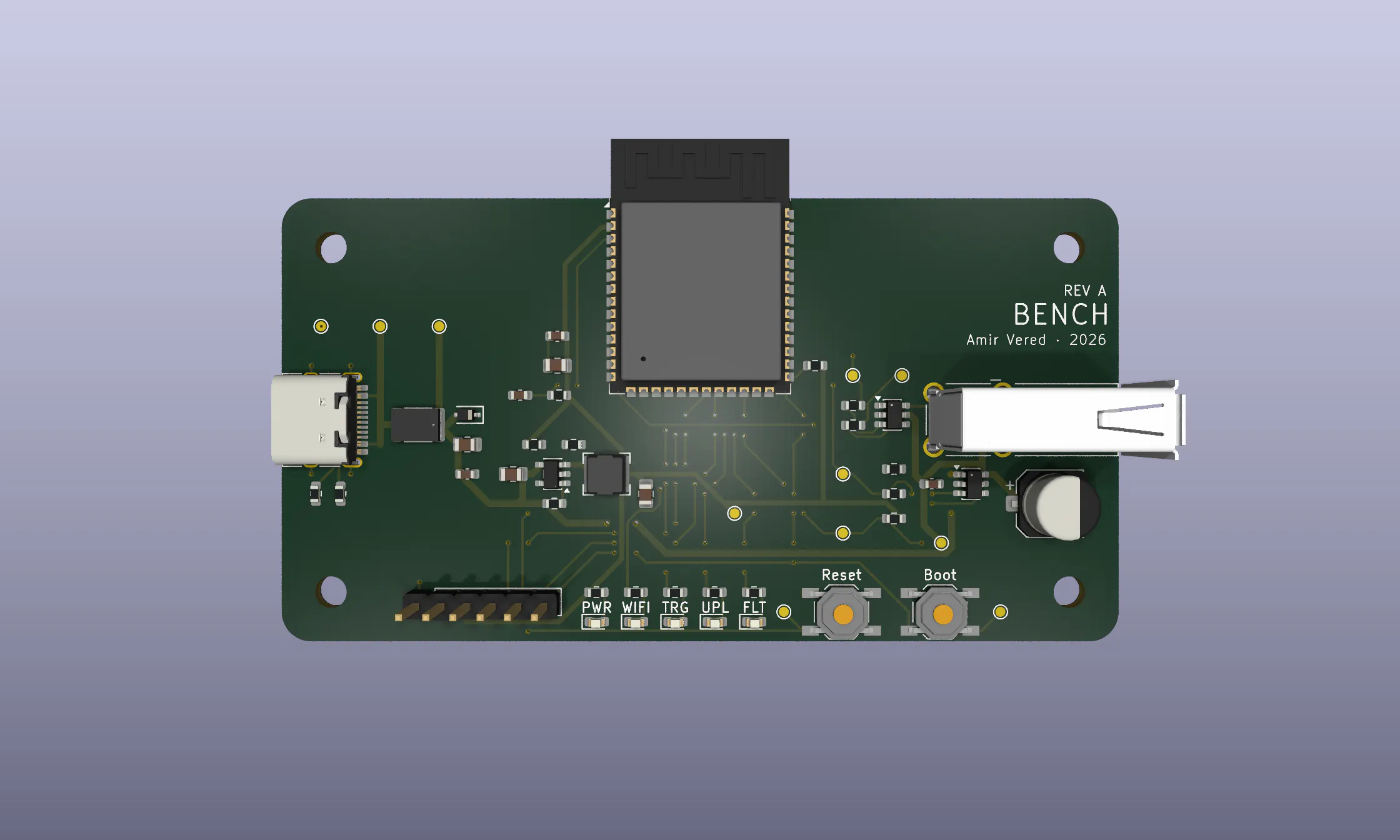
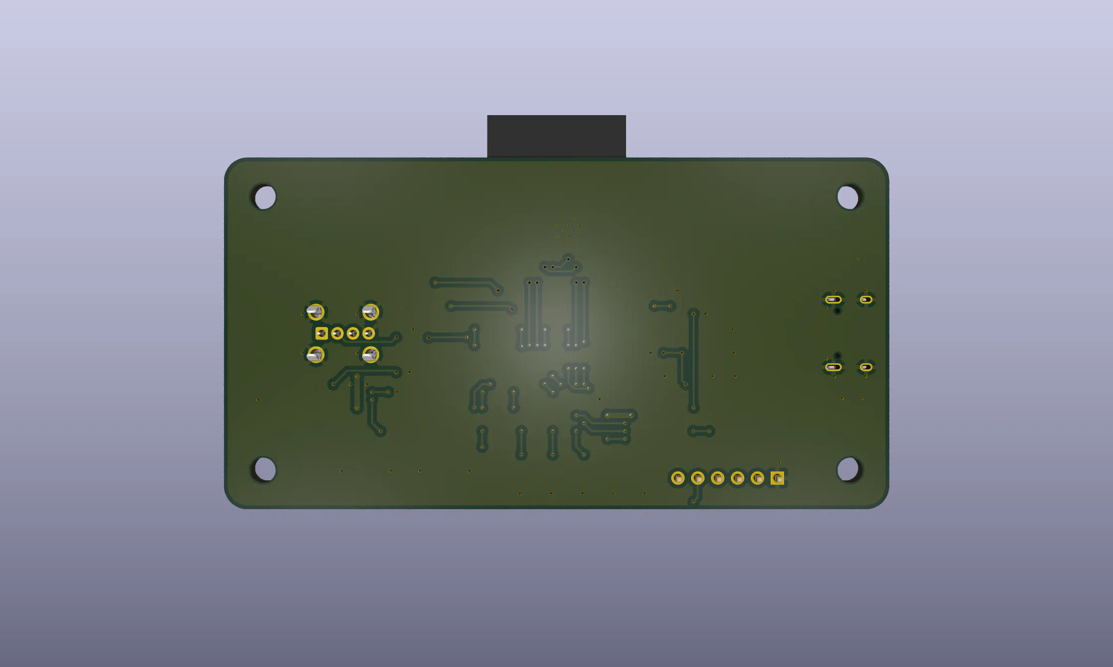
The board is about 85 mm × 45 mm, with rounded corners.
The idea is to have the raw PCB on your desk, so I wanted it to feel a little aesthetic. There’s also mounting holes, so in future iterations, Bench can be mounted into a 3D printed enclosure.
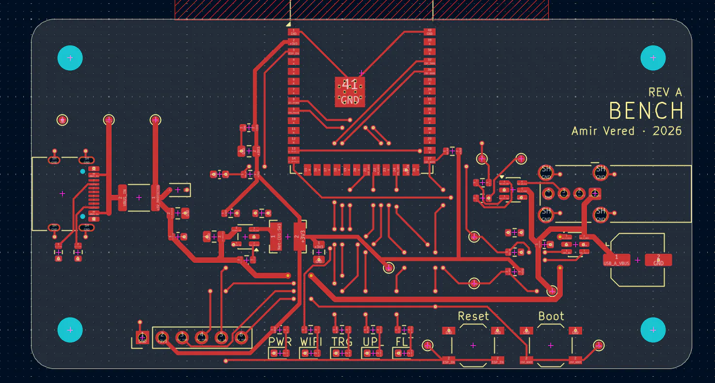
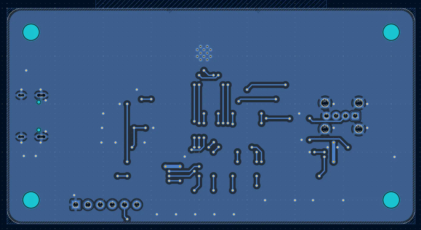
Generally, this is a classic two-layer board, with a ground plane copper pour on the back. The user interface is also placed directly on the front of the board.
Software
Software isn’t the focus of this post, but here’s an overview.
Bench has a few main software parts: a CLI, ESP-IDF firmware for the ESP32-S3, and a mock server (for testing).
The CLI sends status/upload requests; the firmware executes the API calls on the ESP32-S3.
Main API routes:
- GET /api/v1/status
- POST /api/v1/upload
- GET /api/v1/upload/{job_id}
- POST /api/v1/target/power
- POST /api/v1/target/reset
- GET /api/v1/logs
Upload / Bootloader Path
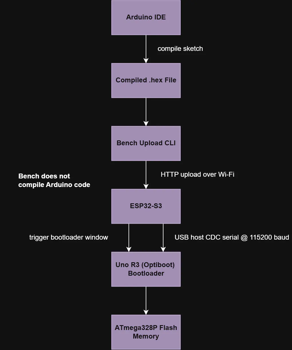
Intended sequence:
- Laptop compiles the Arduino sketch into an Intel HEX file.
- Bench CLI sends the HEX file to Bench over Wi-Fi.
- ESP32-S3 receives the upload request.
- ESP32-S3 opens a USB host CDC serial connection to the Uno R3.
- Bench triggers the Uno R3 bootloader window.
- Bench attempts Optiboot/STK500 communication.
- Bench writes flash pages to the ATmega328P.
- Optional verify checks the uploaded data.
Arduino upload chain:
- Bench USB-A host port
- Uno R3 ATmega16U2 USB-to-serial
- ATmega328P Optiboot bootloader
- ATmega328P flash memory
Considered risks:
- USB CDC connection timing
- Uno reset timing
- Bootloader sync timing
- STK500 command reliability
- Flash write and verify behavior
The firmware builds successfully for ESP32-S3, but I haven't had the chance to test it on hardware, so be careful.
For a more in-depth exploration of the software, check out the repo, linked below.
What I Learned
This project has both elevated my hardware & software skills, while also improving my ability to create in a documented, public, environment.
In terms of hardware and software, this project refined my KiCad workflow, efficiency, and readability. It was also my first time working in the software since 10.0 dropped, so it was a nice chance to acclimate to the new features. Software wise, this was my first time writing complex firmware, so this was super cool. There’s something rewarding about building and then programming a system.
In terms of documentation, this was a great chance to improve my writing, presentation, and speaking skills with regard to engineering. I was also able to focus on creating industry-standard diagrams to improve documentation, while also ensuring my deliverables align with what would be expected in an actual work environment.
What Comes Next
Here’s where we are right now. Rev A is complete, and the docs are robust.